State machine. Animating sprites
- MoltS Xalats
- Nov 20, 2024
- 9 min read
Introduction
In this post, we’ll look at what a state machine is and how it helps us animate sprites. We’ll also introduce the SEV9938, a tool that allows us to design sprites and, in the case of the MSX2, perform the OR operation when two sprites overlap.
What is a state machine
A state machine is a computational model consisting of a finite set of states, transitions between these states, and actions associated with each transition or state. It is used to represent and manage behaviours that depend on particular states and the events that cause them to change.
In our case, we’ll apply it to sprite animation. The state machine will allow us to control the different positions or movements of the main character or any character, depending on user input. Each state will represent a specific posture or movement of the sprite (such as "looking up," "walking right," etc.), and transitions will be triggered in response to actions like moving the joystick or pressing a key.
This way, instead of manually handling every possible state of the character, the state machine simplifies the code by making automatic state changes activate the corresponding animation or behaviour.
In the game Bricks, a state machine controlled by if-statements and key inputs was already in use, but here we’ll use typedef enum and an array to define transitions.
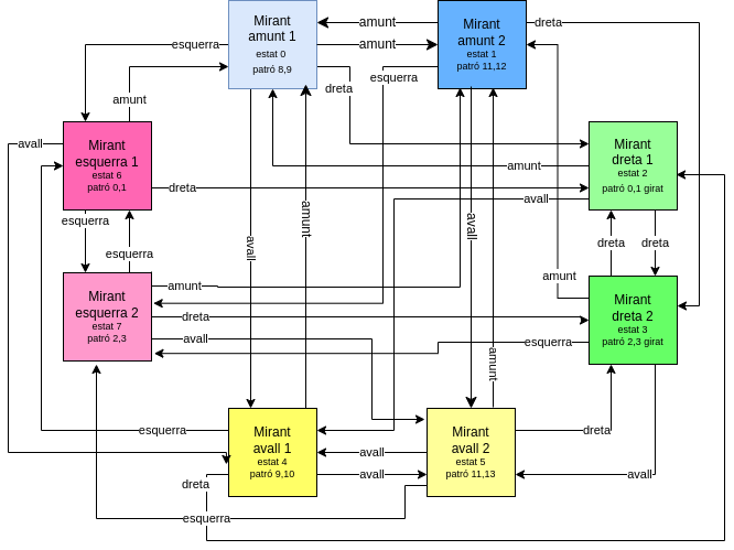
Our main character will have eight states: up, down, right, and left, each duplicated to animate movement within the same direction. You can find this diagram in Imatge 1. The arrows in the diagram indicate the state change according to the key pressed. For example, if we’re in the "Mirant amunt 2" state and press the right key, we’ll move to the "Mirant dreta 2" state. For each state, I’ve also specified the corresponding sprite patterns.
Code
This time, we have a header file created from the SEV9938 data. This header file, Sprites_Joe.h, contains the Sprites array, which defines the 16x16 sprites. Each line specifies 2 bytes and is formatted in binary so that you can easily see the shape they will have on the MSX, as well as because it matches the format used in the SetSpritePattern (char pattern_n, char patternData, char Size) command of Fusion-C. In this command, we first indicate the pattern number, then the address where the pattern starts, and finally the size, which is 16 in this case. So, if we want to load the sprite defined as number 8 into pattern 3, we would use SetSpritePattern(3, Sprites[16*8], 16).
In addition to the sprites, we also have arrays for the colour indices of each line in index_mask and the palette we will use in paleta_bricks. If we refer to index_mask[18], we are pointing to line 3 of Sprite1. Both arrays follow the format for direct use with the Fusion-C functions SetSpriteColors (char spriteNumber, char *data) and SetPalette ((Palette *) mypalette) respectively.
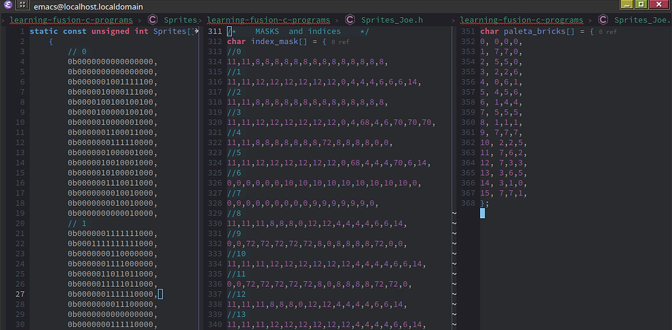
Having explained the header file, let’s move on to discussing the main file, MaqEstatJoe.c. First, we start by including the parts of the Fusion-C library that we’ll be using. This time, we also need to include the previously explained Sprites_Joe.h file. On line 12, we create the global variable processar_mov, which will act as a semaphore to indicate when to process movement in the game.

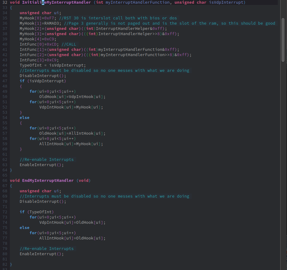
From line 14 to 82, we define the variables and functions to control the Hook of the vertical interrupt of the VDP. This will allow the game to execute periodic tasks, such as checking if enough time has passed to update the sprite's movement.
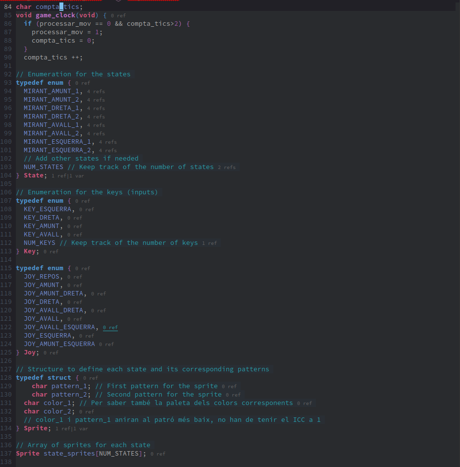
On line 84, we define the global variable compta_tics, which will help manage different timings. For instance, we could update the main character every 2 ticks and the enemies every 3. This variable, along with processa_mov, will be used in the function executed at each VDP interrupt, which simply updates these variables.
Next, we start creating the enumerations that will make the code easily readable. First, we define the different states of our state machine with the State enumeration. It’s important to highlight the last enumerator, NUM_STATES, which indicates the maximum number of states and will be used to set loop boundaries, for example.
The following enumeration is Key, which corresponds to the events defined in the diagram that trigger state changes.
Finally, the Joy enumeration contains the various possible joystick values, starting from 0 (JOY_REPOS) and ending with the value for up-left (JOY_AMUNT_ESQUERRA). This will be used to manage movements read from the joystick or keyboard.
On line 128, we define the structure for the sprite, similar to the groupings called SpriteGFX in the SEV9938. In our case, it only comprises two patterns, as all our sprites involve at most the overlap of two. This structure will store the indices of the patterns used and the corresponding colour indices. Further ahead, on line 265, we initialize this structure, which will clarify its use. Lastly, we create the state_sprites array with this structure.
The next structure is for the main character, which we’ll use to store its position and state. We create the variable Joe using this structure.
On line 148, we have the pinta_sprite() function, responsible for drawing the main character's sprite. Since the main character always consists of two overlapping sprites, we use planes 0 and 1, which have the highest priority and will appear in front of all other sprites. Each plane's colour is set using SetSpriteColors(), and both the patterns and colours are determined by the state. The indices used for colour storage refer to the palette number, so we need to multiply by 16 to locate the corresponding palette for that pattern (line 152). However, multiplying by 16 is equivalent to shifting the byte 4 places to the left, as done on line 153. Byte shifting is faster than multiplication. Another way we could have improved speed is by directly storing the position instead of the palette number. For example, in line 283, we would set state_sprites[MIRANT_AMUNT_1].color_1 = 128 instead of the current 8, and line 152 would become SetSpriteColors(0, &index_mask[ state_sprites[Joe.estat].color_1 ]);, without multiplication or shifting.
The key point comes at line 157, where we define a state matrix. Each state (first dimension) returns the next state based on the key pressed (NUM_KEY). For instance, if we are in the MIRANT_DRETA_2 state and press the KEY_AVALL key (the fourth position according to the Key enumeration), looking at line 161, which handles MIRANT_DRETA_2, we see that the fourth state in the result is MIRANT_AVALL_2. With this simple structure, we can transition from the current state to the next.
Next, we have the functions that calculate the main character's movement based on the keys pressed: moviment_esquerra(), moviment_dreta(), moviment_avall(), and moviment_amunt(). I’ve kept the same names as the functions performing similar tasks in "Scrolling thorugh a tiled screen" for easier integration of the two programs. These functions check if movement is possible (in this case, ensuring we don’t move off-screen) and calculate the new animation state for the sprite.

The next function processes the movement based on joystick input. The up, right, down, and left values are straightforward as they directly correspond to the Key enumeration we have. However, we haven't created specific states for diagonal movement. In this case, I split the movement into two phases: first a vertical movement and then a horizontal one. This approach meant that the lateral animation was always displayed. To address this, I tried alternating between animations in JOY_AMUNT_ESQUERRA, but it resulted in a choppy appearance. A better approach might be to alternate between lateral or vertical animations smoothly.
At the end of the process_input function, we draw the main character's sprite with the newly calculated state and position.
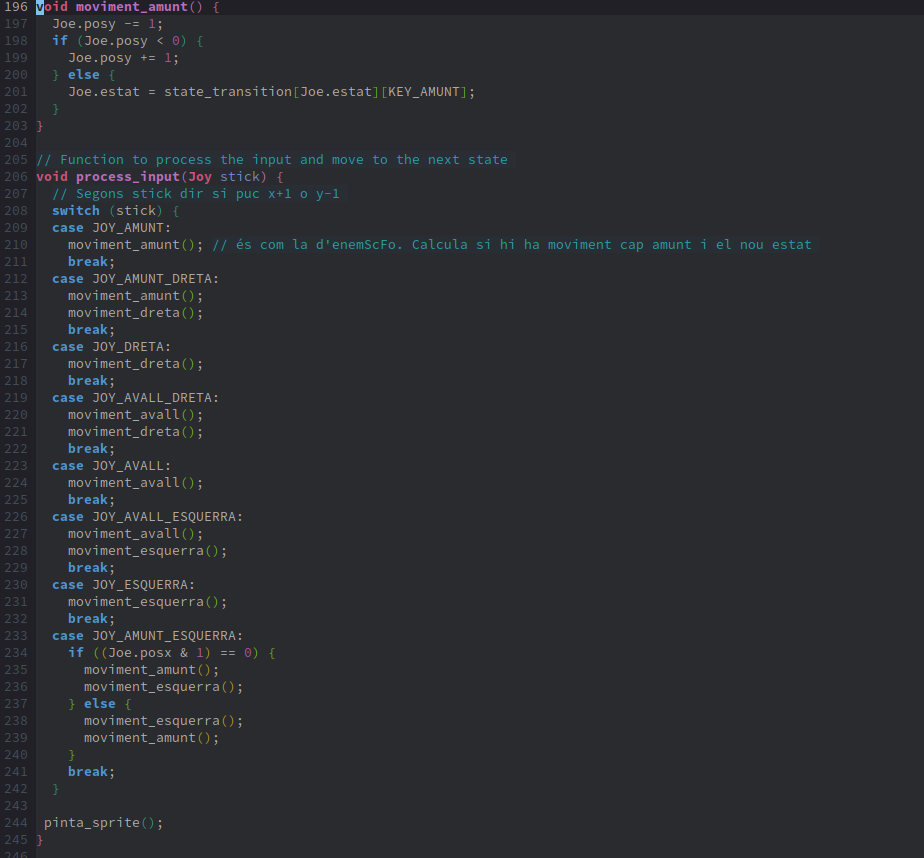
And now we have the main function! We start by setting the screen to `Screen 5` and enabling character movement processing by activating the global variable processar_mov. We enable 16x16 sprite sizes, change the background colour, and load the palette with the colours we’ll use.
On line 257, we initiate a loop to load the sprites from RAM to VRAM so that they can be displayed on the screen. In lines 260-263, we create mirrored sprites for lateral movement. Although we could have directly created them in the program, this method saves RAM at the cost of a few additional lines of code. The function Pattern16FlipVram(char SrcPatternNum, char DestPatternNum, char direction) takes the sprite index we want to copy as its first parameter (indices increment by 4 because we work with 16x16 sizes). The second parameter is the destination pattern number, and the last parameter specifies whether we want a horizontal or vertical flip; in our case, it’s horizontal (0).
Next, we define which patterns and colours each sprite uses. There is a notation interpreted by different C compilers that makes array initialisation more compact, but I couldn’t get it to work with `sdcc`, so I opted for the more verbose method.
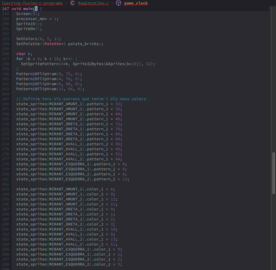
We define the initial position and state of the main character in lines 301-304 and draw it using the pinta_sprite() function.
In lines 309-347, I draw the sprites in their various states. Initially, when I ran the program, all the states were rendered incorrectly, so to diagnose the issue, I decided to print each state separately at different positions to identify the problem. The first issue was that some state patterns were incorrectly assigned, so I corrected the patterns in lines 266-298 to ensure they matched their states.
The other issue was lines disappearing. After consulting the MSX-Lab Telegram group, JamQue suggested that the disappearing lines might be due to colour OR settings. I confirmed this and found it to be true: the lines that vanished were those with the OR operation set for blending colours when overlapping. Reviewing the documentation, I discovered that, as stated in the "Technical Handbook," the CC bit of the colour should only be set to 1 in the plane with the highest number. Thus, if we need to apply an OR operation to patterns in planes 0 and 4, the CC bit must be activated for plane 4. This is evident in the Sprites_Joe.h file, where colour indices above 15 have an offset of 64 to activate the CC bit.
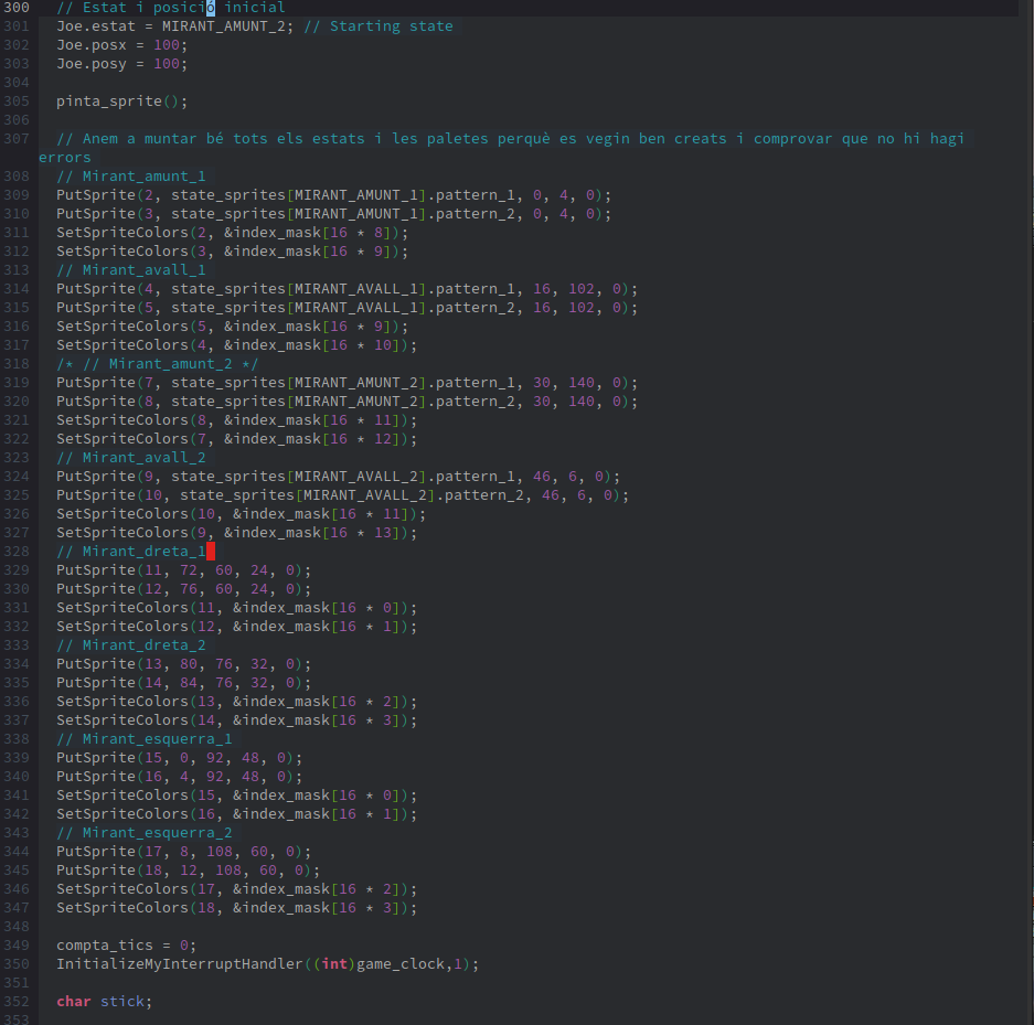
After that, we initialise the compta_tics variable and set up the VDP interrupt, which will run the game timer 50 times per second (or 60 times in the Japanese standard).
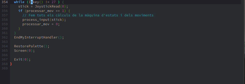
Next, we enter a loop that only exits when the ESC key (ASCII 27) is pressed. In this loop, we read the cursor key or joystick input and process it when the time is right.
Finally, we stop the interrupts, reset the palette, and return to DOS mode 0.
SEV9938 - Sprite Editor
To design these sprites, I used the SEV9938 utility, which has the interface as in 'Imatge 2'. In zone 1, we draw the sprite by clicking or unclicking the pixels to activate them. To the right of this area, there is a column where we indicate the colour index for each line, specifying whether it will use colour 11 or 12 from the palette defined in zone 4. Below this, still within zone 1, there is a tool for copying patterns and inverting or mirroring them. The "Show OR" button displays a table with the combinations of the layers.
In zone 2, we define the `SpriteGFX`, which associates different patterns to form a complete sprite. The highlighted pattern is the one currently shown in zone 1, while zone 3 displays the result of all the overlaps. The name "Sprite GFX 2" can be changed to more descriptive labels, such as "left-side" for clarity. At the top of zone 1, there is a bar to adjust the opacity of the layer, allowing you to see the underlying content of `SpriteGFX` while drawing a new pattern. At the bottom of zone 2, we can rearrange the pattern order and apply an offset to one relative to another.
Zone 3 shows the final `SpriteGFX` result, with the OR operation applied if it is enabled. In the example, the OR effect is visible in the created fist and feet. We can choose to display the OR result, adjust the image size, and change the background colour.
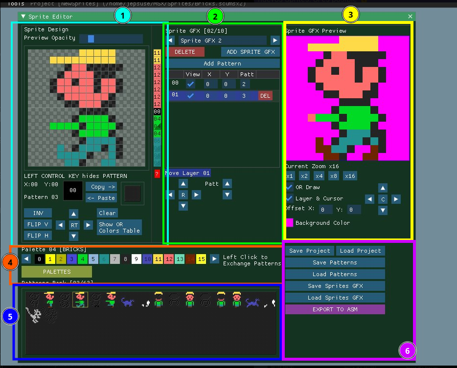
In zone 4, we select the palette using the left and right arrows at the ends of the colour array, and by clicking the "PALETTES" button, we can create a new palette or delete others.
Zone 5 contains the different patterns we have created. Clicking on one will replace the currently active pattern in zone 2. Be cautious, as I’ve often mistakenly overwritten the wrong pattern.
Finally, in zone 6, we have the option to save the project. Currently, there is no built-in export to C, but we can save in the generic .scumsx2 format. This file is a JSON-formatted text file containing all the necessary information. To create the Sprites_Joe.h file, I developed a Python script that converts this file into a .h header file. I manually edited the resulting file to apply the final format seen on GitLab. If you wish to use this script, you can find it here. Feel free to share any suggestions or modifications.
By the way, if you have your `SpriteGFX` arranged in animation order, you can use the arrows in section 2 to switch between them and get a preview of the animation.
Conclusion
This is a basic example of how to create sprite-based animation on MSX using a state machine. One potential improvement would be handling diagonal movement; this could be achieved by adding a new state and managing it through the state machine or by ensuring the character always faces sideways with an animation, using a variable that switches each time it's triggered. Another enhancement could involve merging the Num_keys that change the sprite state and position with the joystick inputs. Alternatively, keeping them separate as they are now might be beneficial for mapping other key combinations to the appropriate Num_keys.
We also provided a brief introduction to using SEV9938 to design sprites, taking advantage of the OR functionality of the V9938 and V9958 chips. This isn't necessary for the graphics9000, as its sprites are entirely bitmapped.
Click here to see the example in action.


Comments